Measurement and test methods
Thoroughly tested: 14 methods for the measurement and testing process
Since the quality of our additively manufactured parts and components is very important to us, we have a very extensive catalog of measures for checking the various parameters. Here is an overview of our in-house measurement and testing procedures, more detailed information can be found below.
Send request >
Contact us >
Micro CT scan
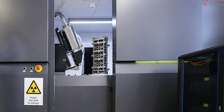
In industrial computed tomography, the inserted component is irradiated and thus sectional images are calculated, which generate highly accurate representations of external and internal contours and are used to analyze the interior of the component. The object is placed in a suitable and fixed position on the manipulator or additionally fixed. After insertion of the component, the tube or detector parameters are set depending on the material, wall thickness or geometry. In special cases, not the complete component, but only an enlarged section, the so-called ROI (Region of Interest), is scanned. The scanning process is non-contact and non-destructive. Any object, any material, regardless of the post-treatment method can be scanned, as long as the maximum wall thickness is not exceeded and thus the beams can still penetrate the component. Depending on the size of the component and the wall thickness, the CT scanner delivers a 2D projection in a short time, which is converted into a 3D volume by a high-performance computer.
For high-performance components with high manufacturing and post-processing costs, it is urgently necessary to check the quality of the component between the individual manufacturing steps. Normally, this is done by specialized measurement service providers and causes a delay of one to two weeks or increases the process costs. FIT has a micro CT scanner that is seamlessly integrated into the quality assurance process so that CT examinations can be performed "on the fly" and comprehensive examination results can be graphically displayed. This saves time and costs.
A second important cost factor is the correct setting of the scan parameters and the positioning of the component. Based on many years of know-how in dealing with CT measurements, the experts at FIT position the component in the measuring room in such a way that the shortest possible transmission lengths are generated and thus the lowest possible costs.
Send request >
Contact us >
Optical 3D scan
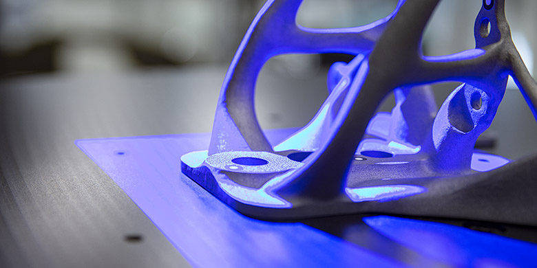
An optical 3D scan is used to perform an exact shape and dimension analysis of a component without contact. In preparation, the component surface is sprayed with a special spray and adhesive dots are applied to the object to ensure that sufficient measuring points are available even for reflective surfaces and undercut objects. Precise fringe patterns are then projected onto the object surface and captured by two cameras using the stereo camera principle. Since the beam paths of both cameras and the projector are known in advance through calibration, up to 2x16 million coordinate points can be precisely calculated from the three different beam sections. The result is complete measurement data without holes or faulty points. The projection unit of the Triple Scan is based on Blue Light Technology. The sensor works with narrow-band blue light so that interfering ambient light can be filtered out during image acquisition. Thanks to a powerful light source, short measuring times are thus achieved.
Send request >
Contact us >
Tactile 3D coordinate measurement
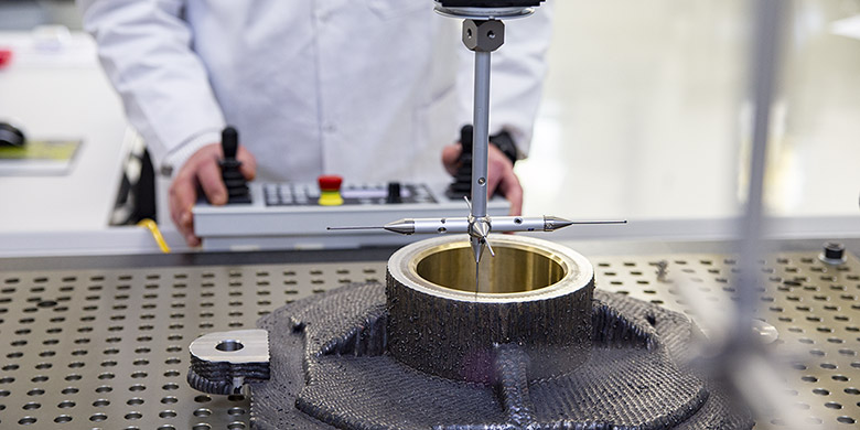
In a tactile 3D measurement, the component surface is recorded point-by-point with precise probes of a measuring system. This is used to determine various geometry elements such as hole spacing, bore diameter, depth dimensions or angles of a workpiece. The measuring probes are equipped with ruby tips and are automatically exchanged by the measuring arm of the system, depending on the measuring task or customer specification, which significantly speeds up the measuring process. Using the main axes in the x/y/z direction, measured values can be determined independently of shape and geometry, again saving time. Tolerance violations can be detected in the shortest possible time.
Send request >
Contact us >
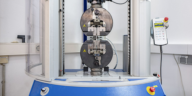
Universal testing method
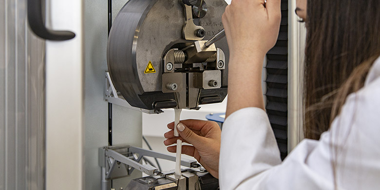
Various test methods are possible for tensile and compression tests with a static universal testing machine (type: Inspect Table from H&P). Depending on the test method, a standard-compliant test specimen is manufactured.
In the 3-point bending test, the test specimen is positioned on two fixed supports and loaded from a third support point from above until the material fails.
In the compression test, the support brackets are removed and the standard specimen lies flat on a plane plate. A second flat plate exerts pressure on the body from above until the body shatters under excessive load. In the static and dynamic tensile test, the specimen is clamped at both ends between two plates specially adapted to the shape of the tensile bar, and force is applied in two opposite directions. In the dynamic tensile test, the tensile test is performed only up to a certain point and then repeated several times. This causes cracks in the material, which causes the material to fatigue. The characteristic values describe the longevity of a material under repeated application of force up to final failure. In the static tensile test, the process is carried out once until the material breaks.
Simultaneously with all tests, a graph records the stress and force progression until failure of the material in order to determine the characteristic values.
Send request >
Contact us >
Hall flow measurement
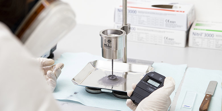
A Hall flowmeter is used to analyze the flow rate of a particular material. Exactly 50 g of a material is weighed out and filled into a cylinder located in a device. The time it takes for the material to flow through a standardized opening into a vessel below is then stopped. The flow rate of the powder is influenced by the size, distribution and surface topography of the grains.
Send request >
Contact us >
Hardness test
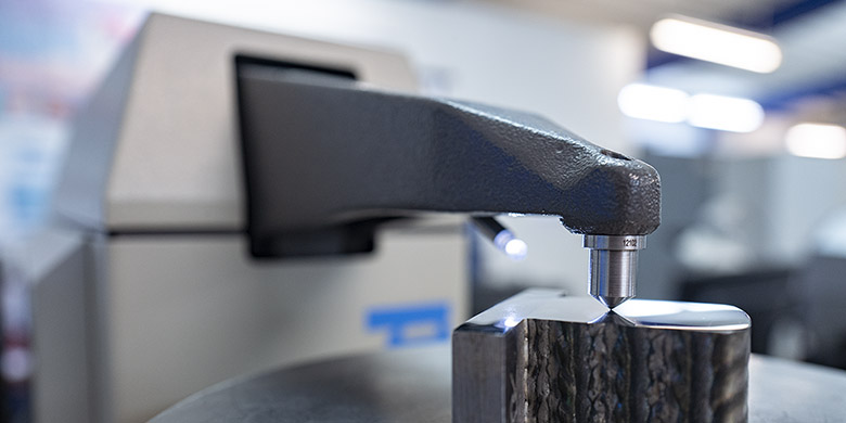
In the hardness test, a test probe penetrates a test specimen, mainly made of soft metals, under the action of static force. The resistance is measured by means of the penetration depth or indentation size of a cylindrical test probe (according to Rockwell) or a ball test probe (according to Brinell). This depth measurement method is most frequently used at the end of a process chain to check the final hardness.
Send request >
Contact us >
Element analysis
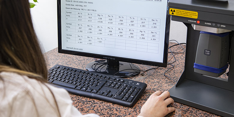
This non-destructive method can be used to determine the elemental composition of various raw materials. When X-rays enter a test specimen, characteristic rays are returned, collected and assigned to elements depending on the type of radiation. Since additive manufacturing processes mainly use alloys, this analysis to determine the composition of all materials to be processed or developed internally is part of a reliable quality control.
Send request >
Contact us >
Light microscope

When inspecting through an optical microscope, the test specimen is examined under an LED cold light source and thus pores, cracks or other defects of the inspected surface become visible. For this purpose, the object to be tested is embedded in fast-curing resin and the surface is polished smooth with a grinding and polishing machine.
Send request >
Contact us >
Roughness measurement
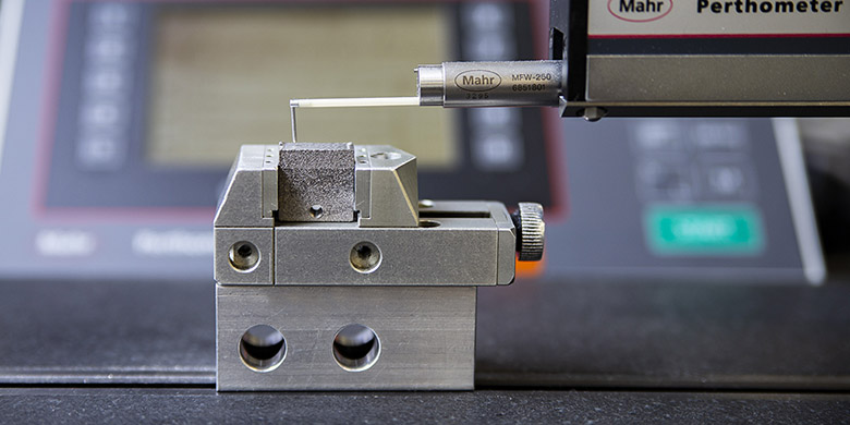
When measuring roughness with a perthometer, a pointed needle is placed on the surface of the test specimen and a standardized distance is traced on the surface of the specimen. Average values for the measurement result are calculated from the transmitted surface roughness profile.
Send request >
Contact us >
2D height measurement
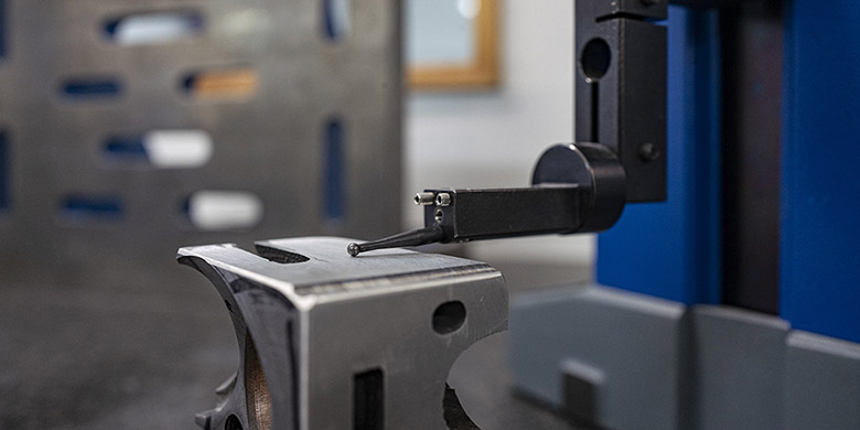
With a 2D height measurement, precise measurements of the component outer contours (max. height 600 mm) can be determined very quickly and checked due to the high repeatability. A test arm with a spherical test probe is located on a static, height-adjustable measuring tower. The component is positioned in such a way that the test probe with the integrated dynamic probe system hits the desired surface during the measuring run and determines this measuring point. This is then repeated at a second measuring point and a measured value is determined.
Send request >
Contact us >
Optical profilometer
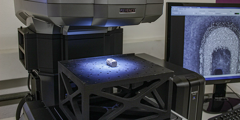
During a surface measurement with a microscope, a fringe pattern from two light sources is projected onto the component (max. 200 × 100 × 10 mm). Elevations or indentations on the surface of the measured object cause the light stripes to be distorted and the shape of the object is determined on the basis of their reflection. In the resulting 3D representation, the line and surface roughness can be determined very precisely (height: ±3 μm; width: ±2 μm).
Send request >
Contact us >
Analytical balance

To determine the density of a body, the analytical balance uses Archimedes' principle. To do this, a density cube (max. 220 g) is weighed on a high-precision balance and in a liquid medium, and the difference between the two weighing results is determined. This procedure is used to determine the volume or density of the test specimen in a fast and simple way.
Send request >
Contact us >
Beam quality measurement
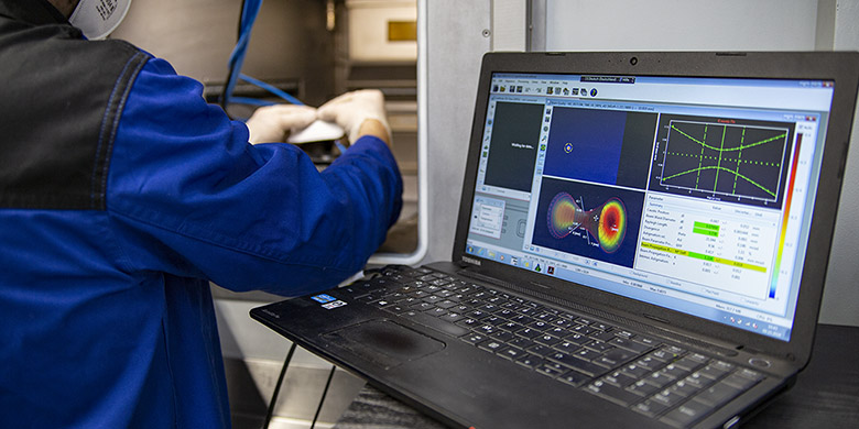
In beam quality measurement, the cross-section of the laser beam (in laser melting) is measured at a specific point in order to determine the laser power and focusability. This shows that the laser beam intensity decreases towards the edge. In technical optics, this is referred to as caustics. These findings are important in the setup and optimization of machine and parameters.
Send request >
Contact us >
Powder analysis
Accurate and fast analyses of grain size or grain shape are important to increase the quality of additively manufactured components. By means of an oscillating conveyor trough, the powder is transported into the measuring device. There, a dust cloud is created by an air jet in front of a two-camera system, and images are transmitted. Image analysis provides insights into the powder particles, which can range in size from 0.8 μm to several millimeters. At FIT, the process is additionally used for incoming goods inspection and machine monitoring.
Send request >
Contact us >
Other links that may interest you:
Selective laser sintering
The most economical process for manufacturing prototypes from plastic.
Learn more >
Innovation guide
Your indispensable compendium on all aspects of 3D printing. Here you will find everything about the various 3D printing processes, finishing options, machine data and application examples from numerous industries.
Free download >


